
BY ANDY SOCCODATO
Establishing, maintaining, and operating from draft are some of the most fundamental skills that any pump operator could be expected to perform.
Many pump operators can achieve their prime through a single intake and with the use of the onboard primer pump. This is generally acceptable for lower flow operations. However, this type of setup is insufficient for larger fire flows and rigs with larger pump capacities.
Related Content
- Drafting Still a Necessary Element on Firegrounds for Many Departments
- What Will the Pumper of the Future Look Like?
- The Battle-Ready Pump Operator: Tricks and Tools of the Trade
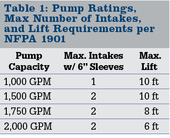
In the modern fire service, many rural fire departments are purchasing pumping apparatus with pump capacities of up to 2,000 gallons per minute (gpm). National Fire Protection Association (NFPA) 1901, Standard for Automotive Fire Apparatus, and NFPA 1911, Standard for the Inspection, Maintenance, Testing, and Retirement of In-Service Emergency Vehicles, require that pumping apparatus using 6-inch hard sleeve with pump capacities that exceed 1,500 gpm be capable of doing so using no more than two separate intakes while drafting. In addition, 1,500-gpm pumps shall be capable of performing with no more than 10 feet of lift, 1,750-gpm pumps 8 feet of lift, and 2,000-gpm pumps 6 feet of lift.
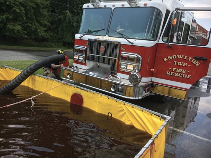
Without knowing this information, many operators are perplexed as to why their brand new 2,000-gpm pumper struggles to achieve 1,000 to 1,250 gpm through a single suction line. The “Twin Tube Setup” is the answer to meeting your pump’s rated capacity in the rural environment while simultaneously building efficiency and redundancy into your water supply system (photo 1).
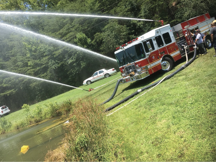
1 A fill site engine flowing its rated pump capacity using the Twin Tube Setup in the rural environment. (Photos by author.)
UNDERSTANDING THE COMPOUND GAUGE
To understand the advantages of the Twin Tube Setup, it is first important to understand what information the compound gauge is really telling the operator. A compound gauge is any gauge that can read both positive and negative pressure (vacuum). On our fire service pumpers, this is the master intake gauge.
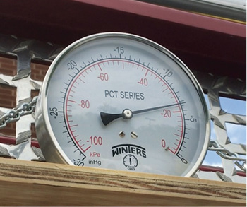
When looking at the master intake gauge, it becomes extremely evident that the positive pressure portion of the gauge consumes the majority of the gauge’s scale, while the vacuum portion only makes up a fraction of the scale (photo 2). However, this tiny portion of the compound gauge can tell the pump operator a great deal of information when operating from a draft.

2 A compound gauge with scale 30 inHg—0 psi to 400 psi. The majority of this gauge’s scale is the positive pressure portion. This gauge is currently reading approximately 15 inHg.
The compound gauges used by the American fire service read in pounds per square inch (psi) on the positive side and inches of mercury (inHg) on the vacuum side. When we discuss hydraulics, often the distinction between psig and psia is made. Pounds per square inch gauge (psig) does not include atmospheric pressure in its reading. Pounds per square inch absolute (psia) takes into consideration atmospheric pressure. For example, at sea level if a pressure gauge on the pump panel is reading 10 psi, that is referring to psig. The psia in this example would be 24.7 psi; we add 14.7 psi, or atmospheric pressure, to the 10 psi that the gauge is reading.
The above example is a great illustration between psig and psia when we are dealing with positive pressure sources. At this point, you may be saying to yourself, “Why does this matter?” or, “What effect does this have on the fireground?” When dealing with positive pressure, this concept does not have an impact on anything we as pump operators do in the real world. However, during drafting operations, understanding this concept allows operators to determine the efficiency of their operation.
It is important to remember that during drafting operations, the pump operator is creating an area of negative pressure within the fire pump that is less than atmospheric pressure. This allows atmospheric pressure to push the water into the fire pump. Determining the psia from a positive pressure source is the result of adding 14.7 psi to our gauge’s psig value. During drafting operations, we must first convert the vacuum reading from inHg to psi, then we must subtract that value from 14.7 psi. This tells the operator how much atmospheric pressure is remaining at the eye of the pump’s impeller during drafting operations for a given flow and through the current setup.
Every 1 inHg is equal to approximately 0.5 psi. Therefore, if our compound gauge is reading 10 inHg, we can convert that into approximately 5 psi. To determine the psia on the compound gauge for this example, we then subtract 5 psi (vacuum reading) from 14.7 psi (atmospheric pressure). The difference in the above example is 9.7 psi—meaning that there is roughly 9.7 psi of atmospheric pressure left at the pump’s impeller.
The goal during drafting operations is for our compound gauge to read as close to 1 inHg as possible—not 30 inHg. The closer to 1 inHg our compound gauge reads, the more atmospheric pressure is available to push water into the pump. The closer the vacuum reading gets to 30 inHg on the gauge, the less atmospheric pressure is remaining at the eye of the impeller, and the closer you are to maxing out your current drafting setup. Since modern fire pumps cannot create a perfect vacuum, your fire pump will cavitate well before 30 inHg is achieved. The maximum your compound gauge should ever read is 22 inHg. This equates to roughly 4 psi of atmospheric pressure remaining at the eye of the impeller.
Another way that we can think about this is in terms of residual intake pressure. When dealing with a fire hydrant, residual intake pressure is the remaining intake pressure after a flow has been established. The closer the intake gauge reads to zero, the less water is available from the hydrant. When drafting, we can think about what the compound gauge is reading in the same manner. The closer the vacuum reading is to 1 inHg, the more water is available through the current setup. As the vacuum reading approaches 22 inHg, the lower the “residual” intake pressure at the pump is, and the closer you are to maxing out your current setup.
In short, the compound gauge tells the pump operator in real time how much work is being done by the pump to achieve the current flow rate. The closer to 22 inHg the gauge reads, the more work the pump is doing to move the current flow rate. The biggest advantage of the Twin Tube Setup is that it drastically reduces the amount of work required by the pump. When we use multiple intakes simultaneously, we are increasing the total area opening into the pump. This means that the total flow is split between the openings and hydraulic loss is dramatically reduced. When the Twin Tube Setup is employed, the operator will notice a huge reduction in the vacuum reading on the compound gauge for a given flow rate (photos 3 and 4).

3 A vacuum gauge reading 20 inHg prior to the second intake being opened. This signifies that the current configuration is close to being maximized.
4 Vacuum gauge reading approximately 7 inHg after the second intake was opened and no changes in the original flow. This signifies that more water is available, or the pump does not have to work as hard to deliver the same volume.
THE TWIN TUBE SETUP
NFPA 1901 and NFPA 1911 both list the conditions pumpers must meet to be able to achieve their rated pump capacities. As noted in Table 1, apparatus using 6-inch hard sleeve with pump capacities exceeding 1,500 gpm are required to achieve these capacities using no more than two intakes. These higher flow rates result in higher friction loss values through the strainer, hard sleeve, and pump body. Since we cannot adjust the atmospheric pressure acting on the water to overcome high hydraulic loss, the only way to achieve these higher flow rates is to use multiple intakes; it is physics, simply put.
Most pump operators only experience this type of drafting operation during the annual pump testing of these larger capacity pumps. It is important to note the difference in setup and operation during annual pump testing and on the fireground. Since pump testing is not a high-stress and time-sensitive working environment, operators can gather the necessary equipment, assemble it, place it appropriately into the water source, and achieve a prime. Conversely, this is almost never the case on the rural fireground.
In the rural environment, we rarely have enough time, equipment, or personnel to establish a Twin Tube Setup from the very beginning. Because of this, the operator must build this system as equipment becomes available. We do not go from zero to octopus; rather, we build our system one tentacle at a time.
The initial goal of the Twin Tube Setup should always be to establish fast, reliable, and efficient water to the fireground. The operator should position the apparatus in such a way that enables him to establish the initial draft using the most convenient intake with the least amount of hard sleeve. This may mean that the initial intake selection could be a front or rear intake.
Using a front and/or rear intake often has a negative connotation during rural pumping operations, mainly because of the flow restrictions associated with their use. However, it is critically important to remember that establishing fast and reliable water in a functional manner should be the initial priority. By using the Twin Tube Setup, the rural pump operator can expand his system to meet higher fire flow demands.
Once the initial prime is established and water is flowing, the pump operator should begin gathering the necessary equipment required to establish the second prime. Often, this requires the operator to pull hard sleeves and strainers from other apparatus operating on the scene. After assembling all the necessary drafting equipment and connecting to the second intake to be used, the process of priming the second intake can begin.
There are several methods for achieving the prime on the second intake. If the operator chooses to use the onboard primer to achieve the second prime, there are a couple of important steps to consider. First, the operator should make the proper notifications to command and other units that are being supplied that the flow of water will be temporarily shut down while the system is expanded. Once these notifications are made and acknowledged, the operator can then shut down the discharge that is sending water to the scene or filling tankers.
At this point, the operator should shut the intake valve to the first intake that was primed. When the intake valve is shut, the vacuum in the hard sleeve between the valve and the water source will be maintained while the second intake is primed—this is assuming that all hard sleeves have gaskets and are tightened appropriately. Now the operator can open the intake valve of the second intake to be primed, throttle up appropriately, and activate the onboard primer.
Once the second prime is achieved, the operator simply reopens the original intake that was primed. After reestablishing fire flow, the operator should notice a reduction in the vacuum reading on the compound gauge. This indicates that the pump is working less strenuously to achieve the desired flow rate. If a higher flow rate is required, it can now be achieved.
THE “PRESSURIZED PRIME” AND THE TWIN TUBE SETUP
Unconventional and alternative drafting methods can also be employed to establish a Twin Tube Setup. The most effective of these methods is the “pressurized prime,” which uses strainers equipped with jet siphon attachments (photo 5). To achieve the second prime, the operator first connects a piece of 1¾-inch hose to the low-level or floating strainer equipped with a jet siphon attachment. Once all of these components are assembled and placed into the water, the operator can connect the 1¾-inch hose to a discharge and the hard sleeve to the second intake to be primed.

5 Low-level strainers with built-in jet siphon attachments to facilitate pressurized priming.
The major difference in using the pressurized prime instead of the onboard primer for achieving a Twin Tube Setup is that the initial intake can remain open during the process. When the operator is ready to achieve the second prime, he simply opens the discharge that the 1¾-inch hose is connected to and throttles up to approximately 150 psi. The operator is now using a portion of the water coming in from the initial intake to achieve the second prime while also delivering water to either the fire scene or the fill site.
When performing the “pressurized prime,” it is critically important to ensure that the pressure on the discharge supplying the jet siphon is maintained to at least 150 psi. The “pressurized prime” method works under the Venturi principle. When the water that is discharged through the small opening of the jet siphon moves at a high velocity, it naturally creates an area of negative pressure that draws the water from the source around it up the hard sleeve and to the intake. Failure to discharge water at a rate of at least 150 psi will not cause the water to move with enough velocity to allow the process to occur.
Up to this point, the intake valve to the second intake should still be closed. The water from the jet siphon is directed up the hard sleeve. However, before the valve to the second intake can be opened, the air trapped within the hard sleeve must be expelled. If the intake is equipped with a bleeder valve, simply open it and listen as the air is exhausted out. When the bleeder is opened, the operator will see the water rise and fill the hard sleeve. The bleeder should be closed once a steady stream of water leaves the bleeder discharge port.
It is critical that the air be bled from the hard sleeve before the second intake is opened. Failure to do so will allow air into the pump, which will cause a loss of prime on both intakes, requiring the operator to restart the entire operation. If the intake isn’t equipped with a bleeder, or the bleeder is located at the bottom of the intake plumbing, the operator must get creative.
To overcome this challenge when assembling this system in preparation for a “pressurized prime,” the operator should connect the hard sleeve to the second intake until he feels the connection become tight on the hard sleeve’s gasket. Then, the operator should loosen the connection a quarter turn. This creates a gap between the hard sleeve, gasket, and intake fitting; the connection is not airtight. When the operator charges the line to the jet siphon, air will immediately be expelled around the fitting. Once water emerges around the fitting, the operator knows that all the air is expelled. The operator now takes his mallet and tightens the connection until water stops leaking from around the fitting (photo 6). The system is now airtight and a prime can be maintained.
Once all the air in the hard sleeve is expelled, the operator can now open the intake valve of the second intake. After opening the intake valve, the pump operator should notice a dramatic decrease in the vacuum reading. The operator should next close the discharge supplying the jet siphon attachment. Once the intake valve is open, the Venturi from the jet siphon is no longer needed to maintain the prime. The pump is now capable of either delivering a higher flow rate or delivering the same flow rate at a fraction of the work previously required.
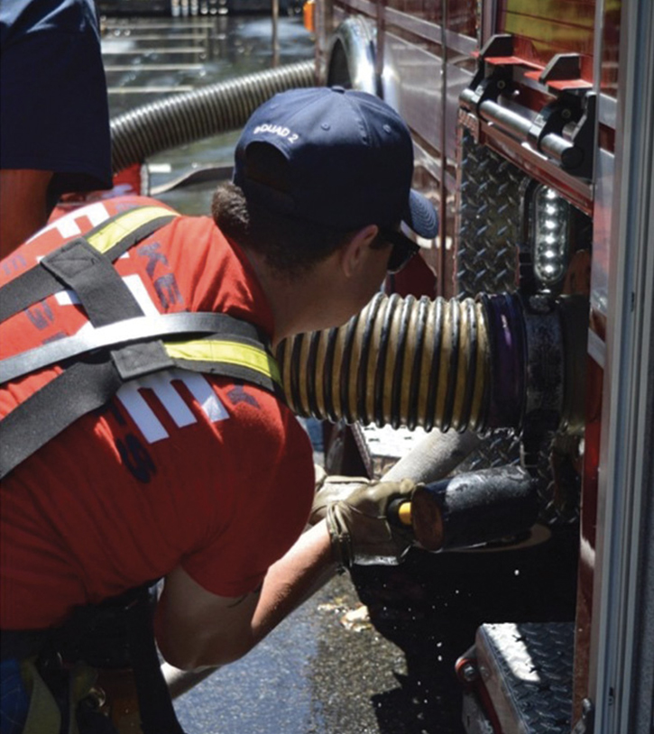
6 This intake valve was not equipped with a bleeder valve. The operator is tightening the connection after pressurize priming the intake and exhausting the air in the hard sleeve.
If the fire flow at the scene is reduced (tactical shifts, overhaul operations) or while awaiting water shuttle apparatus at the fill site, the discharge to the jet siphon can be reopened to flow water and maintain the pumper’s prime. Jet siphons can flow anywhere between 150 and 300 gpm, depending on the manufacturer. By doing this, the operator has created a self-contained recirculation line that does not waste water by dumping it on the ground or wash away the surface that the rig is parked on.
WHEN TO USE THIS CONFIGURATION
The Twin Tube Setup offers many advantages. However, it is important for the engine operator to recognize when this tactic should be employed. Generally speaking, most rural water operations employ two engines that are operating from a draft—the dump site engine and the fill site engine. The question becomes, should both of these engines be employing the Twin Tube Setup?
Most rural water supply operations begin with establishing a dump site close to the fire scene where water shuttle apparatus are able to offload into portable drop tanks. The engine assigned to the dump site is responsible for establishing its draft from these drop tanks and supplying the attack engine. The goal of the dump site engine should always be to position in a manner that enables water shuttle apparatus to approach the dump site, offload, and leave. In the rural environment, this often means either pulling/backing into the driveway or remaining out on the street and establishing a single-lane operation.
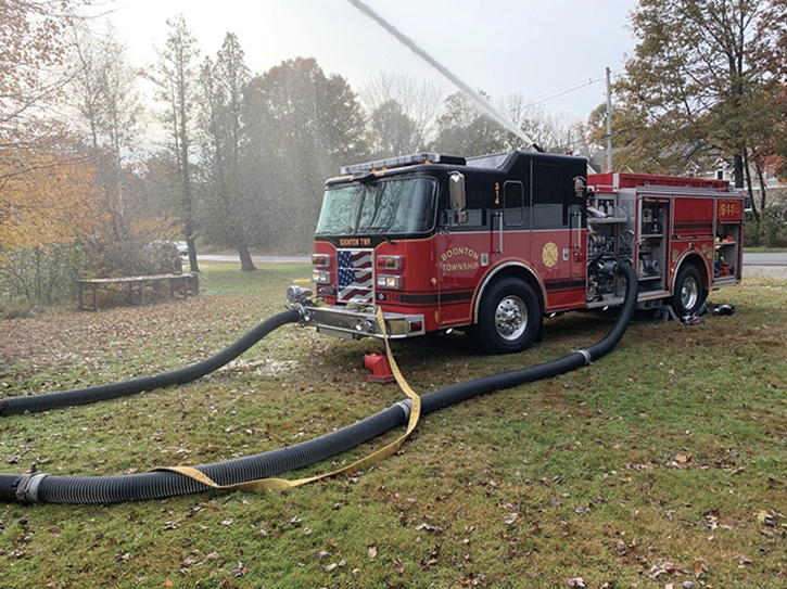
In either of the scenarios listed above, the easiest intake to use initially (if so equipped) is either the front or the rear intake (photo 7). This will enable the apparatus to be positioned to accommodate water shuttle apparatus, use a minimal amount of equipment to establish its prime, and establish water quickly. The biggest tradeoff is the flow restrictions of either the front or rear intakes. Depending on the apparatus, 500 to 750 gpm may be the most that these intakes can supply.
7 This dump site engine is positioned to afford water shuttle apparatus maximum maneuverability while offloading. This places the dump site engine in a position where the front intake is the best option for establishing the initial prime. Should flow demand increase, a Twin Tube Setup can be established.
By reading the compound gauge, the operator will be able to determine if this setup is sufficient for the demand or if it needs to be improved. If the compound gauge approaches 22 inHg, then the operator should recognize that the flow demand is reaching the upper end of the current intake configuration. To rectify this, the operator can employ the steps above to establish a second intake and increase the fire flow demand (photo 8). Now, the limiting factor is no longer the intake configuration of the dump site pumper but the effectiveness of the water shuttle operation.
8 At this fire scene, the initial prime by the dump site engine was established through the front intake, and water was sent to the fire scene. As the flow demand at the scene increased, the operator expanded the system using a Twin Tube Setup to meet the demand.
There may be operations where a single intake is sufficient at the dump site because fire flow demand at the scene is relatively low. However, the engine that is assigned to fill water shuttle apparatus at the fill site should always use the Twin Tube Setup. This is primarily because NFPA 1901 states that water shuttle apparatus be designed to be filled at a rate of no less than 1,000 gpm. This means that it should take a 2,500-gallon tender roughly two and a half minutes to fill completely. Since the fill site engine should always be filling at this higher rate compared with the dump site engine, it is extremely advantageous to employ a Twin Tube Setup to allow the pump to meet this demand without working as hard (photo 9).
9 Engines operating as the fill site pumper should make every attempt to employ a Twin Tube Setup. This will enable the pumper to fill water shuttle apparatus at the target fill rate of 1,000 gpm with minimal strain on the rig.

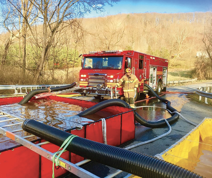
10 An action shot of a Twin Tube Setup operating.
Using the Twin Tube Setup is the easiest and most efficient way to increase your fire flow and build a redundant water supply in the rural environment. With many rural fire departments purchasing pumpers capable of flowing 2,000 gpm, it is absolutely essential that operators understand that the Twin Tube Setup is required to reach these higher flow rates. The operator’s understanding of the compound gauge will help him determine if this setup is required to meet the fire flow demands. Compound gauge readings of 22 inHg indicate to the operator that he is maximizing his current setup and that a Twin Tube operation may be warranted.
It is important to remember that this type of operation is established in stages. The operator should always position the apparatus in a fashion that maximizes its functionality and provides for establishing reliable water quickly. This may mean the operator begins his initial setup using an intake that has a lower flow capacity. Establishing some water quickly is better than no water at all. Should the need for a higher flow arise, a Twin Tube Setup can be built and placed in service without interrupting the initial flow established. On the fireground, the Twin Tube Setup is not intended to go from zero to octopus—it is established one tentacle at a time.
ANDY SOCCODATOhas served in the fire service for the past 13 years. He is a firefighter and driver/operator for the Charlottesville (VA) Fire Department. He is the owner of The Water Thieves, LLC, a training business that specializes in delivering street smart driver/pump operator classes.

