Large-scale firefighting operations require supply pump operators to maximize the flow capabilities from the sources being used. When it’s a fire hydrant, this involves employing a heavy hydrant hookup.
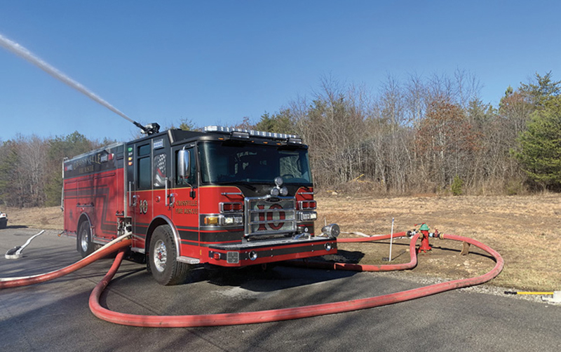
Part 1 of this series examined the variables that affect a fire hydrant’s rated flow capacity—the residual main pressure and the number of outlets used on the hydrant. Part 2 examines the effects that pump operators can expect from double and triple tapped fire hydrants as well as the three major advantages of heavy hydrant operations (photo 1).
- Heavy Hydrant Hookups: Maximizing Hydrant Flows, Part 1
- High-Performance Hydrant Operations
- Maximizing Hydrant Flows Using 6-Inch Soft Suction
- Fire Hydrant Lubricant
- Ratcheting Fire Hydrant and Fittings Wrench
- Hydrant Booster System Brings Hydrants to Rural Areas
- Redundancy in Water Delivery

1 Heavy hydrant hookups are required for maximizing flow capabilities from fire hydrants. (Photos by author.)
Supply Line Diameter
The hydrant outlet area is only one part of the puzzle when attempting to maximize hydrant flows. Another variable that must be evaluated when looking to achieve a hydrant’s full flow potential is the hoseline diameter attached to the hydrant outlets. It usually goes without saying that when connecting to the steamer port of the hydrant, the supply line of choice is large-diameter hose (LDH) (photo 2). However, when it comes to the 2½-inch side ports, many firefighters believe that 2½-inch or 3-inch hose is all that is required. These same firefighters are often surprised when the available flow rate from the hydrant barely increases after connecting with medium-diameter hose.
2 When performing a heavy hookup, it is critically important to use LDH on all hydrant outlets.
When attempting to maximize hydrant flow rates, we must remember that fluids follow the path of least resistance. When double tapping a fire hydrant and attaching a 5-inch LDH line to the steamer port and a 2½-inch line to the side port, the majority of the total water flow from the hydrant will be through the 5-inch line. This is simply because there is less friction, or resistance, through the 5-inch line compared to the 2½-inch line; the water wants to follow the path of least resistance. In this scenario, the operator will see a negligible increase in both the available water and residual intake pressure on the pumper (photo 3).
3 When a 2½-inch line was connected to the side port of the hydrant, there was no noticeable increase in residual intake pressure; this practice is not recommended.
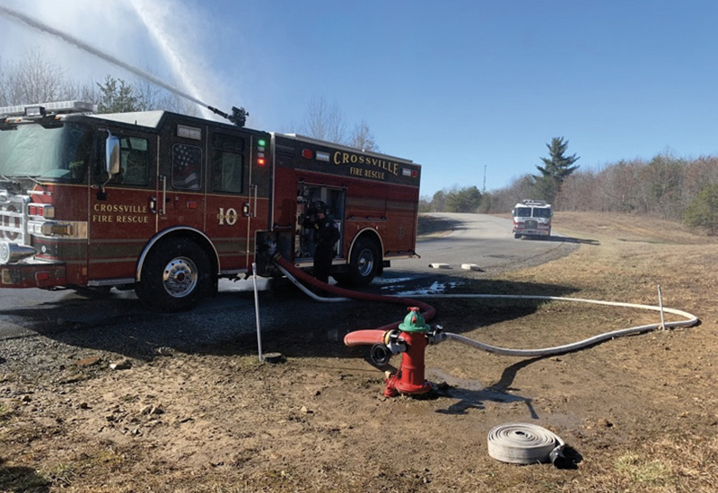
A very different scenario unfolds by simply replacing the 2½-inch line attached to the side port on the hydrant with an LDH supply line (photo 4). Here, since we have attached a much larger supply line to the hydrant outlet, the outlet size of the hydrant becomes the limiting factor with regard to the available water, not the hoseline diameter. This means that more water can flow through the larger lines with less pressure loss. The result will be higher residual intake pressures at higher flow rates.

4 Simply switching the 2½-inch line with a 5-inch supply line resulted in a 60% increase in the residual intake pressure on this Crossville (TN) Fire Department engine.
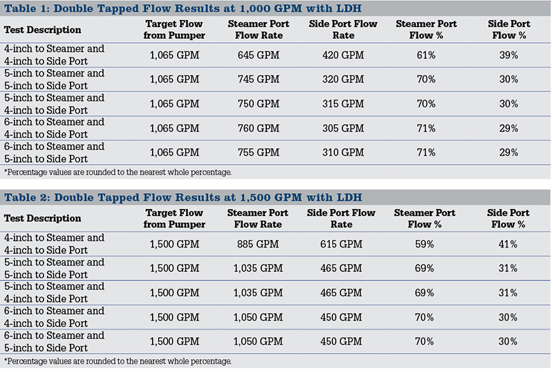
As stated in Part 1, double tapping a fire hydrant is the single most effective way of maximizing the flow potential of a fire hydrant. Over my career teaching this tactic, I have often been asked, “How much water actually flows through the side port on a double tapped hydrant when LDH is used?” This question prompted a series of flow tests to determine what effect, if any, the LDH supply line size had on various flow rates from a double tapped hydrant. During these tests, a flowmeter was placed on the 2½-inch side port of a double tapped hydrant (photo 5). Each test began with a controlled flow through the steamer port only; then the side port was opened while the flow rate from the pumper remained the same. The reading on the flowmeter represented the flow rate through the side port alone. Since the flow rate from the pumper remained the same, the reading from the side port flowmeter was subtracted from the total flow rate, leaving the pumper’s deck gun to determine the flow rate from the steamer port. The results from these tests are listed in Tables 1 and 2.

5 A TFT ShoFlow flowmeter was placed on this hydrant to determine how much water flows through the side port when LDH is used during a double tap hydrant operation.
A very interesting trend emerged after comparing these results. The data proved that as long as the hose connected to the hydrant outlets was larger in diameter than the outlets themselves, the water flow through the steamer port was roughly 70% of the total flow and the water flow through the side port was roughly 30% of the total flow. While this does not initially seem impressive, it is important to remember that the flow rate through a hoseline has the biggest impact on the friction loss within that line. So, when 30% of the total flow rate was removed from the line attached to the steamer port and sent through the line on the side port, the friction loss within the steamer port line was reduced by 50%. This was a huge revelation that explained why operators experience rises in residual intake pressures when opening the side port of a double tapped hydrant.
Division of Labor
There is an important reason this division of labor always followed the 70/30 split when the supply line was larger than the outlet diameter. When we add the 2½-inch side port to the mix, the outlet area increases roughly 30%; there is a direct correlation to the increase in the outlet area and the division of flow within the hydrant. The only time this did not occur was when the hydrant was double tapped with 4-inch supply line (photo 6). In this example, the division of work followed a 60/40 split. This can be explained by the fact that the 4-inch supply line attached to the steamer was smaller in diameter than the 4½-inch steamer port, which made the supply line and not the hydrant outlet the limiting factor. The key here is that to truly maximize the flow capability from a hydrant, the supply line connected to the hydrant must be larger than the outlets to which it is being connected. This truly makes the area of the outlet the limiting factor in the operation.

6 Double tapping is a must for fire departments using 4-inch LDH for their hydrant connections due to the increased friction loss compared to 5-inch and 6-inch LDH.
Tying it all Together
Thus far, we have discussed the differences between residual main pressure and residual intake pressure, the effects of using multiple hydrant outlets, and the effects of supply line diameter on hydrant flow rates. Now, let us examine what happens when we put all of these variables in play together. Table 3 outlines the results of a series of flow tests conducted with the Crossville (TN) Fire Department. The purpose of these tests was to determine what effect fully-dressed hydrants with LDH hose had on the residual main and residual intake pressures when flowing the hydrant’s full capacity.
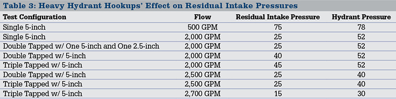
Prior to flowing any water during these tests, the static intake pressure was recorded at 80 psi. Only a single 5-inch supply line connected to the steamer port was used during the first round of tests. The initial flow rate was set at 500 gpm through the single line and was slowly brought up to 2,000 gpm while recording the pressure at the hydrant and the residual intake pressures on the pumper. When the flow rate reached 2,000 gpm through the single 5-inch line off the steamer, the residual intake pressure at the pumper was measured at 25 psi and the pressure at the hydrant was measured at 52 psi. The difference of 27 psi was the result of the friction loss in the 5-inch supply line, the hydrant, and the intake plumbing of the engine. This initial test proved that while we were operating near our “20 PSI Rule” at the pumper’s inlet, we were still well within the safe operating limits established by National Fire Protection Association 291, Recommended Practice for Water Flow Testing and Marking of Hydrants, and the American Water Works Association (AWWA) at the hydrant.
The effects of double and triple tapped configurations were tested next. The first line attached to the side port of the hydrant was a 2½-inch line. When the gate valve attached to the hydrant and the pumper’s auxiliary intake was opened, the residual intake pressure on the pumper remained at 25 psi while flowing 2,000 gpm. This proved that the 2½-inch supply line attached to the side port of the hydrant had no noticeable positive impact on the operation. After these results were recorded, the 2½-inch line was replaced with a 5-inch supply line on the side port. The residual intake pressure on the pumper rose from 25 psi to 40 psi at a flow rate of 2,000 gpm by simply switching the 2½-inch line with a 5-inch supply line.
The switch in the supply line diameter attached to the hydrant side port resulted in a 60% increase in residual intake pressure while the pressure at the hydrant remained at 52 psi (photos 7 and 8). The increase in residual intake pressure means that there is a significant reduction in friction loss within the system. This results in two major benefits to the operator:

7 When this hydrant was double tapped with 5-inch hose, the residual intake pressure rose from 25 psi to 40 psi once the second intake was open while flowing 2,000 gpm. This represents a 60% increase in residual intake pressure.

8 While flowing 2,000 gpm from this hydrant, the pressure at the hydrant remained at 52 psi. However, when a single 5-inch line off the steamer port was used, the residual intake pressure was only 25 psi. By adding a second 5-inch line off the side port of the hydrant, the residual intake pressure rose to 40 psi while the hydrant pressure remained at 52 psi.
- More water is available and the flow rate can be increased.
- If the desired flow rate has already been met, the increase in residual intake pressure means that the pumper does not have to work as hard [higher engine revolutions per minute (rpm)] to deliver the same volume of water.
The next test involved adding a third 5-inch supply line to the last hydrant port while the flow rate remained at 2,000 gpm. When this occurred, the residual intake pressure on the pumper rose from 40 psi to 45 psi while the pressure at the hydrant remained at 52 psi. While a 5 psi increase in residual intake pressure seems negligible, it represents a 12.5% increase in the residual intake pressure at the pumper.
After this test was performed, the flow rate was then increased to 2,500 gpm through both a double tapped and triple tapped hydrant configuration. The results showed that at a flow rate of 2,500 gpm, the residual intake pressure at the pumper dropped to 25 psi when both double and triple tapped configurations were used. In both configurations, the pressure at the hydrant was recorded as 40 psi while 2,500 gpm was flowing. The major takeaway here is that the limiting factor was the size of the 5¼-inch hydrant main valve—not the connections made by the pump operator—in both configurations.
The final test involved taking the flow rate up to 2,700 gpm through a triple tapped configuration. When the flow was increased to 2,700 gpm, the residual intake pressure on the pumper dropped to 15 psi and the pressure at the hydrant dropped to 30 psi (photo 9). The importance of this test was to show that even though we are below 20 psi on the pumper’s intake gauge, the pressure at the hydrant is 30 psi. Therefore, we are still operating within the guidelines set forth by most municipal water authorities and the AWWA. The only way the operator can make this assessment safely is with a gauge placed on the hydrant.

9 Crossville Engine 10 was capable of flowing 2,700 gpm through a triple tapped hydrant configuration while maintaining 15 psi on its intake gauge and 30 psi at the hydrant.
Major Advantages of Heavy Hydrant Hookups
Hooking heavy to a dry-barrel fire hydrant is the single most efficient way to maximize a fire hydrant’s flow capability. When this tactic is used, the friction loss between the hydrant and the supply pumper is reduced tremendously. This results in higher residual intake pressures at the supply pumper, which provides three major advantages:
- More Available Water. The higher the residual intake pressure on the supply pumper, the more water is available to be discharged from the hydrant. As shown in Table 3, when the hydrant was double and triple tapped, the flow rate had to be increased to lower the residual intake pressure to the same value as when only a single 5-inch line was connected.
- Reduced Workload on the Supply Pumper. If the desired flow rate is already being achieved, the increased residual intake pressures provided by a heavy hydrant hookup will reduce the required amount of work needed to be performed by the supply pumper. Since centrifugal pumps take advantage of incoming intake pressure, the higher the residual intake pressure, the lower the engine rpm must be to deliver the same volume of water to the scene. This simple fact during a long operation could result in less fuel consumption by the apparatus, lower the possibility of the apparatus engine overheating, and reduce the chance of a mechanical failure.

10 A heavy hydrant hookup allowed this Southern Pines (NC) Fire Department engine to efficiently flow 2,000 gpm from a hydrant located 400 feet from the attack piece.
- Introduces a Layer of Redundancy. Although we discussed in Part 1 that it is acceptable to let the residual intake pressure on the pumper drop below 20 psi as long as the pressure at the hydrant remains at or above 20 psi, most operators will agree they feel more comfortable when the residual intake pressure is above 20 psi. By maintaining a higher residual intake pressure, we have built a layer of redundancy into our supply operation. It is also important to note that may fire departments currently do not have a means to place gauges on hydrants at every fire. Table 3 proves that the residual intake pressures and the residual main pressures tend to read closer and closer to each other when we double and triple tap hydrants; this is due to the reduction in friction loss in the system. When the ability to put gauges on hydrants is not possible, resort to a heavy hookup operation because the resulting residual intake pressures at the pumper will tend to be higher even at larger flow rates (photo 10).
ANDY SOCCODATO has served in the fire service for the past 15 years. He spent nine years of his career as a firefighter and driver/operator for the Charlottesville (VA) Fire Department. He is a full-time fire instructor II at the Tennessee State Fire Academy, where he oversees the driver/pump and aerial programs. Soccodato is the owner of The Water Thieves, LLC, which specializes in delivering street smart driver/pump operator courses.

