By Bill Adams
Apparatus purchasing committees (APCs) should be aware that indiscriminately choosing a location for a pumper’s rear discharge can have hidden implications in the overall design and ultimate cost of an apparatus and not necessarily just the booster (water) tank.
Concurrently, inadequate purchasing specifications describing a rear discharge’s location can result in not achieving the level of performance from a rear discharge a purchaser expects but failed to adequately describe. Some purchasers are not aware—nor do they care—how water gets from a midship pump house to a rear hose connection. They should.
Tim Dean is president and founder of Pro Poly of America, Inc. (Pro Poly), a custom fabricator of thermoplastic water and foam tanks as well as thermoplastic apparatus body and components parts that is starting its fourth decade in business. He has provided some generic insight into general booster tank construction. He points out thermoplastics of various blends and methods of construction are pretty much an industry standard for water and foam tanks for the fire service.
Basic Tank Types
Dean: “Most pumper booster tanks sit on the chassis frame rails. The tank’s width just fits between the inner rear wheels. When viewing the tank from the rear of the apparatus, if the tank’s side walls extend straight up full height of the tank, it is called a ‘bulk’ tank. That particular design is used when apparatus have full-depth high-side compartments on one or both sides.
“When the tank’s lower vertical side walls only extend upward about 12 inches to 16 inches to just above the rear tire height and then extend outward about 14 inches to 18 inches over the rear wheels, the tank is commonly called a ‘T’ tank.
“The most popular style tank Pro Poly sells is the ‘L’ tank, which can be in a bulk or T configuration. It’s called an L-shaped tank if it has an upper and lower lid. The lower lid is usually in the rear and the upper lid is usually in the front. The L-shaped tank is very popular with departments seeking a low hosebed height.”
Figure 1.
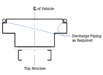
Piping runs in notches in a tank’s upper outside corners—commonly used for a preconnect on each side of the hosebed that terminates just below the hosebed floor. (Figures courtesy of Pro Poly of America.)
Figure 2.
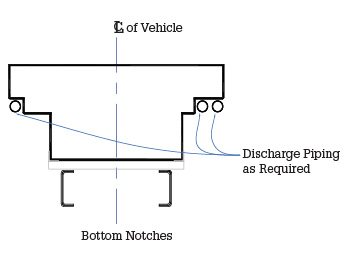
Rear piping in notches in the outer lower corners of the tank’s upper T. This location puts the actual hose connections just above the height of a low-side equipment compartment—possibly reachable from ground level.
Figure 3.
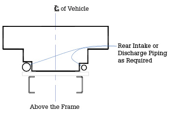
Piping that is notched into the lower outer corners of the tank’s bottom. This location is commonly used for large-diameter hose (LDH) connections.
Figure 4.
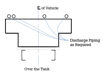
Piping run above the tank. Pro Poly’s Tim Dean says most thermoplastic tanks are designed to hold a certain weight per square foot and the supports for an entire hosebed above the tank must meet these same criteria.
Figure 5.
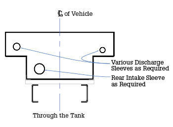
This view shows approximate locations and sizes of through-the-tank sleeves.
Figure 6.
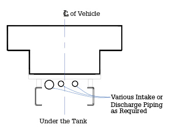
This view shows that piping running beneath a tank requires extensive modification of the tank support cradle. Depending on the chassis components, this location could put piping for LDH connections around waist level.
Dean points out that a tank’s front to rear length is contingent on its capacity and the rig’s overall height requirement—both determined by the apparatus manufacturer (OEM). Placement on the chassis and basic tank design are the apparatus OEM’s responsibility. Ensuring the tank’s construction meets National Fire Protection Association (NFPA) guidelines and the OEM’s basic criteria is the tank manufacturer’s responsibility. It is imperative they work together.
Rear Pipe Routes
There are six basic piping routes from a midship pump house to the rear of a pumper that may require customized tank fabrication and possibly determine how the tank is mounted and secured in the apparatus. One is when a top outer corner of a tank is notched for pipe passage. One is when a lower outer corner of a tank’s “T” is notched. Another is when a lower side wall of a tank just above the frame is notched. Yet a very common method is to provide round “sleeves” running through the entire length of a tank.
An uncommon method is raising the entire hosebed up and running piping above the tank below the hosebed. Another is raising the entire tank up and running piping underneath it. There are several ways to run piping to the rear of a pumper that do not require customization of the tank or its methods of retention. One is to run piping inside the hosebed just above floor level. Another is to run piping through a side exterior compartment and wheel well area.
Dealers in the field may not always explain the various methods and ramifications of each. They should.

1 One of CustomFIRE’s standard hosebed support structures that also serves as a tank hold down. (Photos 1 and 2 courtesy of CustomFIRE.)

2 A typical picture frame type tank cradle that limits fore-to-aft and side-to-side tank movement.
Tank Retention
Dean points out that third-party tank manufacturers have specific tank mounting specifications that must be followed by the apparatus OEMs. They are minimum requirements, and OEMs often exceed them. Tank mounting and retention methods are not the domain of purchasers and are not subject to negotiation. They are described here for informational purposes. Some purchasers opt to include them in purchasing specifications to show favoritism to a tank manufacturer. When seeking competitive prices where OEMs use multiple tank manufacturers, don’t write proprietary mounting and retention specifications for one tank manufacturer and expect the others to change theirs.
Some basic tank retention requirements generically paraphrased from Pro Poly’s installation instructions include the following:
- The tank should be installed to allow it to be secure but also free floating—so it can expand and contract with different weather patterns and not affect the tank integrity.
- The tank must be adequately supported, contained, and held in place to prevent forward-to-aft as well as side-to-side movement and vertical movement.
- Failure to follow mounting instructions will void the tank warranty.
- The tank must be supported on a tank subframe incorporating linear and cross members spaced to not allow for more than X square inches of unsupported area.
- A minimum X-inch space must be provided between the tank side walls and the apparatus compartment walls as well as between the tank and any frame or body component.
- The tank must be isolated from the subframe through the use of rubber strips with minimum dimensions of .X inches by X inches with a minimum Rockwell hardness of X durometer.
- One method to prevent side-to-side and fore-and-aft movement is the use of vertical angle brackets on all four corners. Another is to use a picture frame type structural enclosure to encompass the entire tank bottom. There must be a .X-inch spacing between the tank and the enclosures.
- The tank is designed to be free floating; however, it must have hold-down restraints to minimize movement during vehicle operation, especially when it is empty. Retention can be incorporated into the hosebed floor structure or through a system of angles bolted to the side walls of the body spaced X inches apart and a minimum of .X inches above the tank top to prevent it from lifting up.
[Dean is emphatic that purchasers understand each tank manufacturer has retention features specific to their own product. In fairness to all, the exact dimensions, sizes, and types of structural members and definitive locations are not promoted or endorsed in this narration. Let them tell their own story.]
CustomFIRE
Luca Drayna, a design engineer at CustomFIRE, provided the following description of how that apparatus manufacturer addresses tank retention. “CustomFire uses a full perimeter mounting ‘picture frame’ style support structure consisting of 304 grade stainless steel angle. The front and back of the tank structure is also equipped with a full width front base plate. All stainless cradles are then welded to the stainless steel apparatus body subframe structure.
“The structure is also tank-specific and provides support in the areas and locations specified by the tank manufacturer. All mating areas between the tank and structure are lined with rubber cushion material on the horizontal and front surfaces in addition to the sides and back vertical surface. This allows the tank some space to flex inside of the cradle to prevent any damage to the tank.
“We also use multiple double-break flange reinforced tank retainer/hose load support beams, spanning between and bolted to the inboard apparatus body sides. These beams are constructed of body matching material, profile is to be of minimum height to maximize hosebed depth, and the beams are to be positioned no more than 20 inches apart. This is what helps secure the tank from coming out of the picture frame support structure during travel of the apparatus.”
Purchasing Specifications
As previously alluded, it may not be necessary for purchasers to detail tank mounting and methods of retention unless they intend to favor one tank manufacturer over another. The actual location of a discharge may be of greater importance.
A possible specification could read: “Bidders shall provide an optional price to provide one 2½-inch discharge at the left rear of the apparatus.” Depending on where each bidder opts to locate the discharge, there may be significant differences in pricing. Most bidders will choose the least expensive route.

3 The rear view of a “T” tank with two piping sleeves and horizontal through-the-tank ground ladder storage. (Photos 3-6 courtesy of Pro Poly of America.)

4 The front view of another “T” tank with sleeves. The height of the fill towers indicates this rig will have a very deep hosebed.

5 A rear view of a “T” tank with two sleeves and horizontal ground ladder storage.

6 A front view of an L-shaped tank with a “T” on only one side of the upper portion. The arrows show tabs under each sleeve where the apparatus OEM can secure the piping routed inside the sleeve.
Although the specification appears to be direct and straightforward, the description is woefully inadequate to describe the operational and performance requirements that may be expected. How? Is the discharge intended to be located beneath a particular hosebed? How much lower? What is the desired height of the discharge from ground level? Is there adequate spacing from lights, grab rails, access ladders, and beavertails to allow connecting a gated wye on the discharge—or even using a spanner wrench?
Purchasers should not be influenced by a what could be a variation in cost. Ensure a location that is firematically beneficial for the life span of the apparatus. The intent here is not to promote one location over the other because of cost. It is merely to show there can be price differentials based on location, especially when an OEM must modify its standard hosebed and booster tank support structures.
Not addressed but extremely important is that different rear discharge locations may require modifications in pipe and valve sizing to overcome friction losses and achieve desired flows—if flow requirements are stipulated in the purchasing specifications.
Interview with Tim Dean
Dean reiterates that many items mentioned here are for educational and informational purposes only and are not subject to “change” by purchasers. For that reason, some items are not included in either purchasing specifications or advertisements. Just knowing how tanks and rear piping are intertwined can assist buyers in making purchasing decisions.
- What is the most popular tank capacity? “Pro Poly’s most popular size is 1,000 gallons, followed by 750 and 500 gallons. Most have integral foam tanks.”
- Is there a common sleeve size for through-the-tank piping? “The most common is a 4-inch internal diameter polymer pipe welded in place. A 2½-inch pipe takes up close to 3 inches of space. That is why tank manufacturers typically use a 4-inch sleeve to give a bit of room to plumb and not have the 2.5-inch pipe wear and tear the pass-through sleeve during the service life of the tank.”
- Should purchasers specify the sizes for sleeves and notches in tanks? “No. Sleeve and notch sizes are the responsibility of and coordination between the apparatus and tank manufacturers. Each may have proprietary requirements.”
- Are there limitations when locating sleeves and notches in tanks? “Absolutely. The various methods of tank construction dictate the final location of sleeves and notches to allow sufficient room from tank walls for welding. Purchasers should compare and evaluate each tank manufacturer’s technical specifications prior to selecting a tank supplier for their apparatus purchase.”
- Should pipe or flexible hose sleeved through a tank be “secured” at each end of the tank? “In general, that is a question for the apparatus OEM. Most tank manufacturers do not want to have wear and tear on their tanks. When piping passes through a sleeve or tightly in a notch, most tank manufacturers want the piping secured so it doesn’t vibrate and cause abrasion on tank components. Pro Poly often welds strips of polymer on each end under the pass-through sleeve so apparatus OEMs can secure the pipe.”
. . .
Dean reiterates it is essential that tank manufacturers assist apparatus manufacturers in achieving goals such as ensuring flows to rear discharges, minimizing friction losses, and determining front-to-rear chassis weight ratios and centers of gravity. Coordinating rear discharge piping and booster tank interface can ensure rear discharge locations enhance safe and efficient fireground operations.
BILL ADAMS is a member of the Fire Apparatus & Emergency Equipment Editorial Advisory Board, a former fire apparatus salesman, and a past chief of the East Rochester (NY) Fire Department. He has 50 years of experience in the volunteer fire service.

