
By Bill Adams
“Apparatus Purchasing: Drawings and Blueprints, Part 1” (September 2022) explained the value of blueprints and drawings in designing and building fire apparatus, especially when advancing an idea drawn on a bar napkin to a finished product.
Now let’s discuss the methodology and tools used in the process. There is no single accepted definition in the fire service for either blueprints or drawings, so consider them one and the same.
Fire apparatus articles are usually authored by marketing and salespeople from the corporate side of the apparatus industry and by current and past fire service members. When commentary includes sophisticated and technical data, some writers are in uncharted waters. There’s a possibility of regurgitating unfamiliar and misinterpreted data, thus inadvertently confusing or misleading readers. That scenario can exist when purchasers write apparatus specifications requiring blueprints with terms they may have misunderstood. Lukas Drayna, the lead engineer at CustomFIRE Apparatus in Osceola, WI, has provided some manufacturer’s engineering perspective to my commentary.
- Apparatus Purchasing archives
- Apparatus Purchasing: Detailed Specifications Are Needed—Sometimes
- Apparatus Purchasing Committee: Needs vs. Wants
- Apparatus Purchasing: Easy or Hard?
- Apparatus Purchasing: Revisiting Purchasing Specifications
- Apparatus Purchasing: Steps and Specs
- Apparatus Purchasing: Read Between the Spec’s Lines
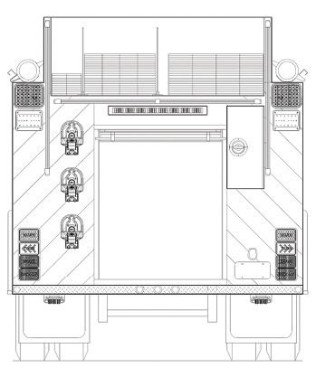
1 A 2-D rear view drawing of a basic pumper. Simple drawings like this are effective working tools in the field, albeit with limitations. (Photos 1 and 2 courtesy of Frank Riccobono.)

2 The same pumper drawing view with arrows pointing out obvious errors. Basic two-D programs do not self-correct “data entry” errors.
Three fundamentals in the fire truck world are buying, selling, and manufacturing. Most purchasers want apparatus built their way. Some are oblivious to, or are uncaring of, the difficulty and cost. Manufacturers (OEMs) and salespeople (vendors) look at profitability—as they rightfully should.
Degreed engineers, designers, and draftsmen (engineers) employed by the OEMs are neutral participants. They only look at the physical dynamics. Can the apparatus be built safely and legally while complying with all applicable regulatory standards and established engineering practices? The unfounded wrath of both buyer and vendor is often directed at the engineers for merely stating a simple fact such as, “No, it can’t be done.”
Dimensional Drawings
The adage “A picture is worth a thousand words” means a photograph or an illustration is better than a written description when describing an object including fire apparatus. That has merit, providing the picture hasn’t been Photoshopped. On the other hand, an illustration is a visual aid—a rendering of what something might look like.
It is the purchaser’s responsibility to define exactly what a drawing is to show. Drawings and blueprints should only be evaluated based on meeting those explicit requirements. Those requirements can vary per application. Drawings can be specifically oriented for sales presentations, bid proposals, preconstruction meetings, and postconstruction approvals.
Highly detailed and often proprietary engineering (construction) drawings are seldom, if ever, disseminated until a contract is signed. Because there is no single definitive fire service description of drawings, it is advisable purchasers and vendors predetermine them—preferably at a prebid conference.
Almost all fire apparatus blueprints are two-dimensional (2-D), meaning they are flat views showing, as an example, the length and width but not the depth or thickness of an object. Explaining three-dimensional (3-D) drawings is complicated. When researching a simple definition for them, confusing terminology was found such as visual and aspect analysis, multiple vanishing points, isometrics, and graphical projections. My paraphrasing of combined multiple online definitions of 3-D drawing resulted in defining it as, “a technique of drawing a 3-D object on a flat surface.”
2-D
Drayna: “2-D sales drawings, as I refer to them, are very helpful but can be dangerous tools if the user is unfamiliar with the product. Since we are unable to see what is going on with the other side of the truck, we don’t know what issues we might be causing by adjusting the compartment heights or adding a transverse sleeve.”
Taking Drayna’s “dangerous tool” description one step further: It can be problematic when an apparatus purchasing committee (APC) member has enough computer savvy to make a rudimentary 2-D computer-aided design (CAD) drawing of a fire truck. It can be embarrassing when a vendor in the field has equally limited capabilities. Both can look foolish.
Frank Riccobono, a 4 Guys and HME-Ahrens Fox salesperson, provided some examples. Illustration 1 is the rear view of a pumper; 2 shows the same view with purposely made errors. The upper rear scene and warning lights are reversed, the right-side tail light assembly ended up inside the hosebed, the auxiliary steps are now inside the compartment, and one length of hard suction hose is stored underneath the rig through the mudflap and rear tires.

3 Three views of a large tandem axle rescue truck. This is a working print, indicated by the notations to verify equipment sizes. There’s probably a second print showing the top and front views. Manufacturers are only obligated to show features as specified in purchasing specifications. Often, minute details of internal structural components and unnecessary measurements can complicate a drawing. As an example, is it necessary to show the actual distance from the bottom of a tank to the top of a frame rail? What about the distance from the bottom of a hosebed to the top of a tank? (Photos 3-8 courtesy of CustomFIRE.)

4 This side view print of a pumper, sans dimensions, is a stepping stone to a 3-D print. Is a purchaser’s priority showing the equipment layout? A close examination of this print shows some actual “usable” compartment door heights rather than internal compartment measurements. Which is more important?

5 This 2-D side view print of a commercial chassis tanker shows that a single view does not necessarily give a 100% representation of the unit. Recently, much of the single-sheet literature passed out at trade shows is showing fewer features.
An APC member bringing such a flawed print to a committee meeting could likely be embarrassed and ridiculed by his peers if the vendor points out the obvious errors. The vendor might have made an enemy, especially if the member thinks that just because he can draw what he considers a blueprint, the manufacturer should be able to build it. Likewise, if the vendor provided a similar print with glaring errors, his credibility and ultimately the sale may be lost— despite the good intentions. 2-D drawings are excellent sales tools, albeit with limitations. They don’t show depth; they’re not self-correcting, and they are not necessarily engineering drawings.
OEM-supplied 2-D drawings do not always reflect a complete representation of a proposed apparatus. OEMs are only obligated to provide the number of views and features a purchasing specification requires (illustrations 3, 4, and 5). OEMs are understandably hesitant to provide proprietary methods of design, engineering, and construction for an apparatus that has not been sold.
Drayna: “Our sales department uses a basic 2-D platform to accurately draw full-size renderings of the trucks for the customers. This helps them visualize compartment loadouts and overall sizing of the apparatus. (Note: Drayna said 2-D drawings are renderings and are not necessarily engineering drawings.) There can be times that something looks good on a paper sketch or even a 2-D drawing, but until it has been fully designed into the apparatus, we cannot guarantee it will work in the desired location or orientation. Changing one detail on an apparatus can create a snowball effect regarding the final design that committees may not think about at that timeframe, such as changing the tank capacity or compartment volume.”
3-D and CAD
Drayna: “Our engineering department uses the 2-D drawings as a reference to create 3-D models. The 3-D models allow the OEM and customer to realize how much space is available for their equipment and if there are shortfalls in the original plans. A great part about CAD is the opportunity to move and change designs on the fly. When a customer asks to move a feature, we can show them the alternative layout in a matter of minutes. The attention to detail allows the customer and OEM to be confident in the end product. We always send our customers final 3-D layouts prior to sending the truck to the laser to ensure they are happy with the look and configuration of their apparatus.” (CustomFIRE uses an all-bolted body construction where all bolt holes for fabrication and accessory mounting are laser cut prior to assembly.)

6 This driver’s-side rear ¾ 3-D view of a full response cab and body gives a clearer representation of the rig than a flat, one-side view.

7 A passenger’s-side rear ¾ 3-D view of a pumper with a rear-mounted pump.

8 A driver’s-side front ¾ 3-D view of an industrial foam pumper on a tandem custom cab and chassis.
Drayna continues: “We use multiple CAD programs during the sales and manufacturing process of each truck sold. These programs have become an essential part of the fire apparatus building process. CAD is able to provide us with accurate design details and quick on-the-fly adjustments as desired. We have been using 3-D modeling since 1994.”
Computer Numerical Control (CNC)
CNC and CAD are generic terms that are not proprietary to any one OEM, although some CNC and CAD programs can be. Depending on the complexity, an investment in CNC and CAD technology can be a million-dollar investment.
Drayna: “Our advanced CNC software is essential to ensure all components fit in the provided areas and to allow our laser to precisely cut every hole in the sheet metal in the proper position. CNC is a group of software programs where every part on a fire truck’s drawing is assigned a control number. This type of programming can create precision fire truck parts. Our software has thousands of hours programmed into the models to ensure our design allows the manufacturing team to be able to successfully assemble every engineered product provided to them.”
Engineers/Designers/Draftsmen
Drayna: “The size of a company really differentiates the technical skills required by the engineers, draftsmen, and designers. In larger companies, there can be many tiers of CAD-based employees working together to complete a common goal. Draftsmen typically create detailed part drawings with specific dimensions that companies are able to reference back on for years to come. I have come across drawings older than myself that we still use today. A designer typically holds a degree in engineering or an engineering technology focus that normally uses CAD programs to design the truck. Engineers are the ones who ensure the apparatus is designed and built following all safety measures and regulatory codes. They understand the technical aspects and impacts a design change can make. Intricate builds such as aerial devices require the services of a certified engineer also known as a professional engineer to sign off on the design. Many tests must be passed to receive the professional engineer title.”
Specification writers should tread very carefully if they specify the “acceptable” qualifications of prospective bidders’ engineering staffs. That could be considered overly restrictive to the point of limiting competition and showing favoritism to a particular vendor.
Review
Drayna reviewed my interpretation of statements and questions referencing technical blueprint jargon and commented in terms understandable to noncomputer-savvy readers.
- 2-D side views of fire apparatus only show length and height. “Yes; however, some rear views can show depths if drawn correctly.”
- Autocad means CAD. “No, CAD means computer-aided design. It is a nonproprietary process. Autocad is just one of many software programs used in the CAD process.”
- Isn’t Autocad a computer software program that helps design stuff? “Yes, but it only does so in 2-D. Software programs have various levels of performance. The earlier basic programs do not generate material lists.”
- Are 2-D Autocad views self-correcting if an operator mistypes a compartment dimension? “That is incorrect; the program will not automatically correct itself.”
- Is there only one CNC program? “No, there have been ongoing improvements and new software programs, such as Pro/ENGINEER, SOLIDWORKS, and Creo, that incorporate 3-D modeling.”
- Are CNC programs foolproof? “Newer software programs are only as efficient as the data loaded into them. The less that is modeled in the design, the more that has to be created by hand.”
- Will newer software programs automatically correct 3-D drawings? “Yes, BUT it requires programming upfront to make parts work together.”
- But don’t the newer programs “talk to each other” and generate materials lists and the exact parts and pieces to be fabricated from the preestablished CNC control numbers? “Not exactly. Some computer programs are smart and can generate lists within their own program, but it takes multiple interacting software programs to design and fabricate a fire apparatus.”
- When customized changes are made to an existing part number such as changing the location of a grab handle or a warning light, are those changes entered into the computer and a new control number established, thus increasing the menu of part numbers available for future builds? “It depends. For some manufacturers, this is true. Others reuse control numbers to reduce the number of parts they have to manage, allowing the same control number to have multiple configurations.”
Specifications and Workers Prevail
Almost every purchasing specification stipulates if there is a discrepancy between the specifications and the drawings, the specifications prevail. Caution: Blueprints often make note there may be a plus or minus variance in the prints’ dimensions and the actual product.
Blueprints and drawings are invaluable tools when evaluating the apparatus being proposed and specification compliance. The actual benefit depends on the cooperation between buyer and seller and their mutual understanding of what is required on the prints.
There is no doubt blueprints generated by CAD and CNC programs are a boon to fire apparatus design and efficient manufacturing. However, do not disparage or discount the value of well-trained and experienced workers “on the floor” who can ultimately determine a quality build—regardless of the size and expertise of an engineering staff.
BILL ADAMS is a member of the Fire Apparatus & Emergency Equipment Editorial Advisory Board, a former fire apparatus salesman, and a past chief of the East Rochester (NY) Fire Department. He has 50 years of experience in the volunteer fire service.

