By James Flanagan
The Plymouth (WI) Fire Department, like many departments with a rural fire exposure, found the need to improve its rural fire protection class rating. Currently, its rural rating is a PC-8B. The goal was to achieve at least a PC-6 to provide relief to businesses and homeowners on the cost of their fire insurance premiums.
Like many departments with volunteer members, a committee was formed whose makeup could tap the members’ varied backgrounds from engineering to IT specialists, all of whom proved beneficial in the project.
The committee’s firefighters began with training sessions presenting various fire flow formulas and general background knowledge of friction loss and the factors affecting fire flows through hoses and appliances.
A PowerPoint® program on the basics of the ISO rating system was developed and presented to the committee and later to the entire department. The presentation focused on many criteria used in gauging a department’s adherence to the elements that compose the fire service’s 50% portion in the ISO PPC rating schedule. Also presented were the components for dispatching (10%) and water supply system (40%) in the municipal sector.
The committee’s approach to the project was to develop data that would benefit not only the Plymouth Fire Department but also many others within the county. To develop valid and repeatable data, some additional testing tools were needed and developed to provide the means to test and validate some of the committee’s hypotheses. A water depth test gauge was developed to convert the increase or decrease of water levels in our portable drop tanks to gallons.
The committee set about confirming that the department’s drop tank’s depth could be converted from depth in inches to gallons. Initially, this was done by taking a container that, when filled to the appropriate level, contained 50 gallons. Then, 50 gallons at a time, the drop tank was filled to a level of 500 and 1,000 gallons, with each depth noted and marked in the tank’s inside surfaces.
These measurements were converted to cubic feet and then multiplied by 7.47 gallons per cubic foot. The department’s drop tank measures 12 feet 8 inches × 12 feet 8 inches × 30 inches high, which converts to 100 gallons per inch of water depth.
The interior surface of the drop tank is now marked and labeled with 500-gallon increment levels.
The initial objective was to analyze the consumption requirements of our current jet siphon system. The Plymouth Fire Department uses a manufactured unit that is placed into the female end of a 6-inch draft hose 12 feet long, which directs a stream of water into the center portion of the hose that discharges through a 7⁄8-inch orifice supported by a 1¾-inch handline. This system generates a venturi-like effect that draws additional water by means of the partial vacuum it creates in the immediate area of the discharged stream.
Initially, a problem arose when we placed the system on the ground outside of the drop tank. A portion of the stream backflowed from the draft hose. The leakage was significant enough that the loss had to be accounted for if we were to obtain an accurate flow rate. The team found that by placing the pickup end into the top of a 5-gallon pail, the water was captured to a point that it remained level and did not overflow the pail.
At this point, we were able to run our flows and be assured that the discharged amount of water could be measured with no loss to be accounted for. Depending on a department’s system design, some type of capture vessel may be required if you run a similar testing evolution.
Having determined that we could measure the amount of water flowed by measuring the change in the depth of the water in the tank, we made a simple depth gauge from 2-inch (inside diameter) clear PVC plastic pipe 60 inches long, or twice the height of the drop tank; a 2-inch end cap; a reducing fitting (2 inches to 1½ inches); a couple of 2-inch-diameter fish bobbers; and a dowel.
We glued the reducing fitting to the bottom end and drilled it with six small ¼-inch holes to allow the water to enter into the column. The end cap for the top should have a small hole, less than 1⁄8 inch, drilled in it. We found that too large a hole would not dampen the bobber’s movement in response to small wave actions on the surface. We found that the glue seam of the two halves of the bobber was not perfectly aligned, so we had to carefully sand the overlaps flush to allow it to fit within the tube and still retain a distinct color line. We removed the bobbers’ fishing line attachment systems. This provided a recessed opening on the button end. An appropriately sized dowel can be inserted or glued into the bobbers, with one bobber placed on each end of the dowel. The dowel’s length should be such that when the tank is empty, the red/white seam rests at the same height as the top of the tank frame.
The red/white seam at the top of the bobber will be used to mark the start and stop points. To mark these points, blue painter’s tape was applied to the outer surface of the tube, and the marks were easily read when the measurements were recorded. We found it necessary to begin with the tank filled to about the 500-gallon level. Also, remove any ripples at the tank’s bottom so it is sitting flat to ensure that its shape is constant.

1 The drop tank with gallons marked. (Photos by author.)
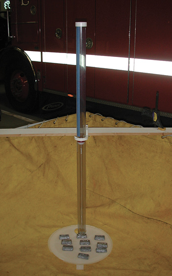
2 The PVC gauge in the drop tank.
Our initial setup consisted of supporting a single jet siphon by means of a single 50-foot 1¾-inch handline. The supply line and its flow originated from two locations, initially from a 2½-inch side discharge equipped with a 2½-inch gated wye gated to two 1½-inch discharges. The initial support pressure was at a pump discharge pressure (PDP) of 75 pounds per square inch (psi) and was timed at five minutes. This was performed on three consecutive trials and was found to provide a consistent volume/quantity of water.
The same sequence was then performed from the apparatus’s front 1½-inch discharge through the 1½-inch gated wye through a 50-foot 1¾-inch handline. This was again performed for three consecutive five-minute trials with the measurements recorded in inches (we measured to the nearest 1⁄32 inch) and converted to volume/quantity, finding them to be consistent with that of the previous trials.
The Plymouth Fire Department standard operating procedure for rural operations uses the engine’s front 1½-inch discharge to support the jet siphon system. This served to resolve the questions for why one outlet was preferred over another on our apparatus. As the pump piping on any particular apparatus may differ, it would need to be confirmed for each unit tested. Ours was found to have a generous diameter of hose and metal piping.
We selected a range of pressures (75, 100, 125, and 150 psi) and ran three five-minute flows at each pressure. While it may appear that running these tests took only 15 minutes, it was not so. The flows were controlled at the wye, and opening and closing were done quickly and in coordination with the stop watch operation. After each timed flow, there will be a wait time for the water to settle down to where the bobber’s movement can be limited to a very narrow range of movement, selecting the midpoint of the movement once the range is small enough. The pump throttle was not changed; water was recirculated into a second tank. You would want to simulate your fireground operations where the relay engine will be using jet siphons to move water between drop tanks while drafting water from the main tank to support an attack engine at a workable pressure.
The gallon-per-minute (gpm) flows found in Figure 1 were found to be significantly lower than what we were expecting. For example, a 7⁄8-inch-diameter tip with a nozzle pressure of 100 psi would develop a flow of 227 gallons. When running the formula to solve for the square root of the nozzle pressure, we arrived at 14.44 psi at the tip of the jet siphon discharge at our PDP of 100 psi. Adding in the friction loss of 5.78 psi in the 50 feet of 1¾-inch hose, the remaining friction loss is attributed to the pump discharge piping with the various 90-degree elbows to the front bumper-mounted 1½-inch swivel outlet, the wye, and the turbulence/friction loss resulting from the 90-degree welded joint on the jet siphon. The question at this point was how this could affect our next series of tests where two jet siphons would be supported.
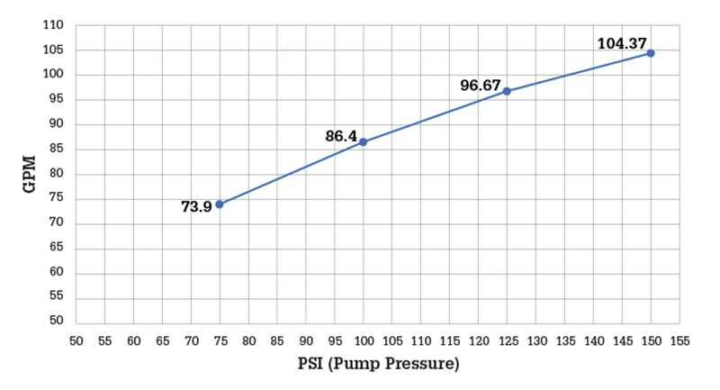
Figure 1: Jet Siphon Test Single Line
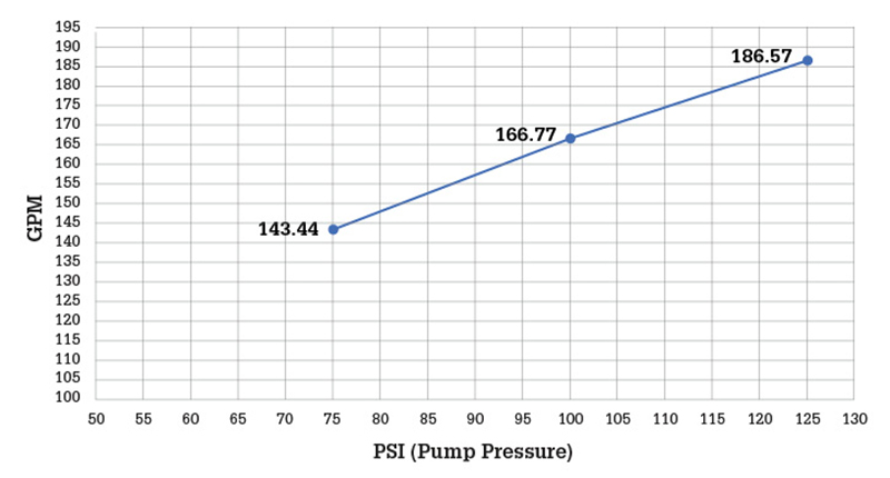
Figure 2: Jet Siphon Test Dual Line

Figure 3: Jet Siphon Test Single Line Transfer Total Volume
An identical jet siphon assembly was attached to the wye. Three identical tests were run at three of the four PDPs used in the previous test cycles. The 150-psi test was excluded, as we felt that such operating pressure would cause problems of its own and would create unneeded risks during operations. Because of the additional volume being generated in the tank after two tests, we had to partially transfer back water and separately identify the next start and end marks on our gauge. This was where the painters tape proved to be easily added and removed between tests.
Having established the system demands, the committee set about determining the transferred volumes at various pressures. Having determined that the dual-siphon and single-siphon flows varied little, the transfer volumes were determined on a single-siphon setup. The results of these tests were to determine a range of operating pressures and the expected transfer volume at those pressures that can be supported in a two-drop-tank deployment. As with our initial single-system tests, these tests were done at all four operating pressures. After our first test at 75 psi PDP, we found the volume of water transferred, when added to the more than 500-gallon starting volume in the drop tank, required us to shorten the time frame to three minutes for each evolution at the higher pressures as well to transfer back water down to the starting level. Figure 3 shows the average results of each test pressure. The system’s ability to move meaningful additional water plateaued past the 125-psi threshold.
The ability to supply and maintain a large volume of water places a great deal of responsibility on the operator to transfer water between tanks at a pressure that would far exceed all but the longest relays while needing to set a higher PDP to support the jet siphon and at the same time sending water to the fireground at a pressure that can be managed by the attack engine operator. Communication between operators and understanding the supply line friction loss and residual pressure needs of the attack engine should minimize many of the pressure issues.
While the committee assumes the measurements and results it developed may be equipment- and setup-specific, it feels the process used is valid and can be duplicated whenever equipment is changed and can be rerun for updating generated charts. As water transfer systems can be as varied as the colors of apparatus, and as a department may have dissimilar units within its own inventory, we believe an understanding of the abilities and limits of those systems can make for better fireground decisions when looking to match the needed fire flow with the ability to move the required volume of water.
JAMES FLANAGAN recently retired from the Plymouth (WI) Fire Department after serving for 46 years. He has also served as an adjunct instructor at the Lakeshore Technical College (Cleveland, Wisconsin) and is past president of the Wisconsin Society of Emergency Services Instructors.

