By Edward Collet
Part 1 looked at the main instruments providing feedback to operators. Part 2 follows the stream of water from the intake to the discharge, examining the control systems it contacts along the way.
INTAKE VALVES
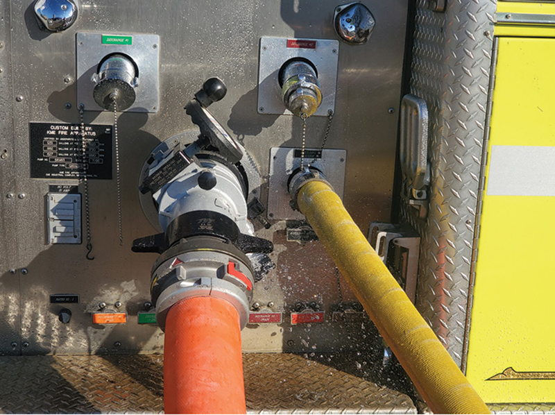
The first controller water encounters is the intake valve; these can be internal or external. The intake valve controls the flow of water into the pump. It allows tank water to be used to battle a fire while the supply line is connected. Without a valve, the supply line must be connected before tank water can go to the pump; otherwise, it will take the path of least resistance and go to the ground.
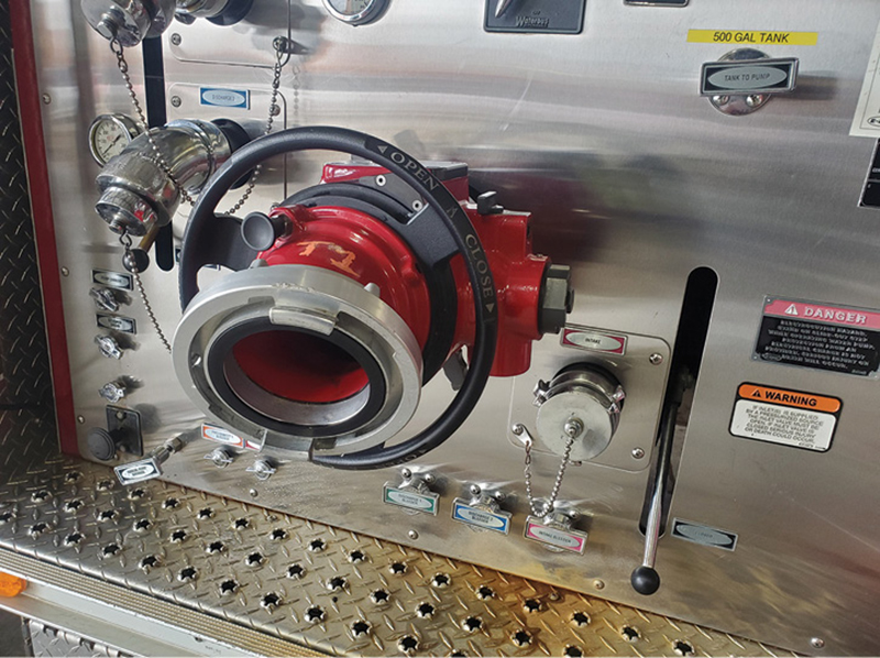
External valves are most popular, as they can be easily replaced and incorporate the intake relief valve and air bleeder. The two main designs of external intake valves are the ball intake valve (BIV) and the piston intake valve. The valve of a BIV is essentially a quarter-turn ball valve, but instead of having a full ball, the valve face is a quarter of a hollow sphere. This maximizes sealing surface while minimizing the interface between moving and nonmoving parts. In a piston intake valve, a piston slides up or down to control the flow of water. While both styles should be exercised on a regular basis, it is critical to do so with a piston intake valve because of the potential of sticking caused by sediment and contaminants in the water. It is not unheard of for piston intakes to seize to the point where the operator breaks off the hand wheel trying to open the intake.
Another external intake valve is a simple butterfly valve. This style is popular in rural settings where drafting is common. The butterfly valve provides the same size intake piping as the pump intake waterway. Since it is used in drafting, no relief valve is built in, and if there is a vent valve, it is very small.
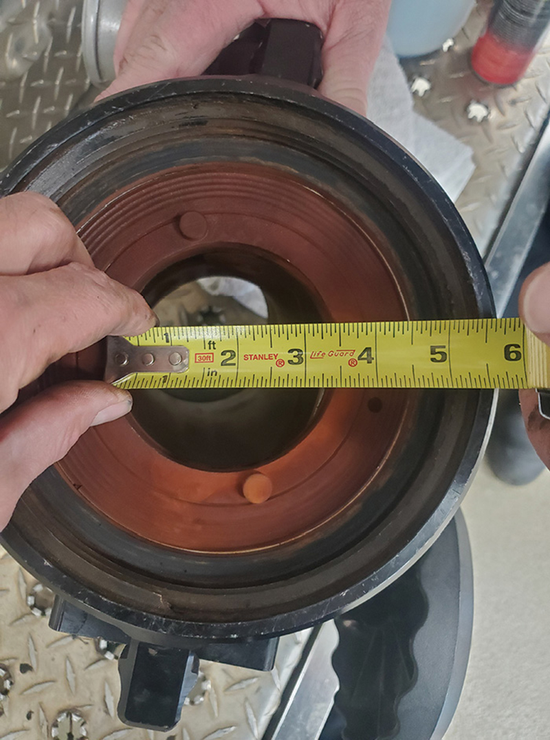
It is important to know the waterway size of an external intake valve. It may be connected to 6-inch intake piping and allow for connecting 5-inch large-diameter hose (LDH), but the waterway may be less than 4 inches in diameter. Some older intake valves have waterways as small as 35⁄8 inches. It is important to flow test the pump through the intake valve to understand the potential flow restriction it could impart. This is a reason to evaluate all water appliances when purchasing a new apparatus. Does it make sense to save a few thousand dollars reusing an old intake valve, which may limit the shiny new half-million-dollar 2,000-gallon-per-minute (gpm) pump to 1,500 gpm or less?
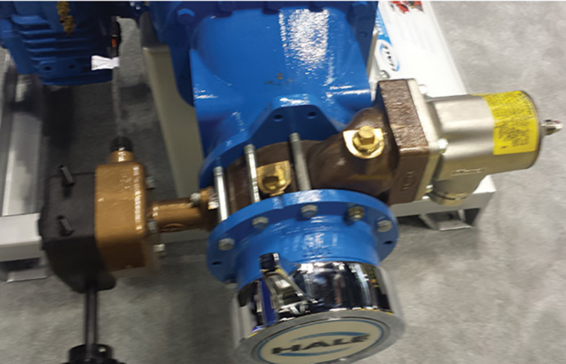
The other style of intake valve, called the master intake valve (MIV), is located behind the pump panel. The MIV is a motor-actuated butterfly valve in the main intake piping. These valves have a manual override should a problem occur with the electric motor. Some MIVs are air-actuated instead of electric, but this is a small percentage of MIVs on the road. Like the external valves, exercise the MIV regularly. If the butterfly plate sits against the gasket for a long time, there is the potential for it to set. If the plate sets to the gasket, often the torque of the motor is not sufficient to open the valve, and the manual override will be needed to break the set.
PRESSURE RELIEF VALVES
Incorporated with external ball intake valves and plumbed in separately upstream of MIVs is the intake pressure relief valve. All intakes greater than 3 inches in diameter must have a relief valve per National Fire Protection Association (NFPA) 1900, Standard for Aircraft Rescue and Firefighting Vehicles, Automotive Fire Apparatus, Wildland Fire Apparatus, and Automotive Ambulances, 13.6.6 (2024 ed). The main purpose of this relief valve is to protect the supply line. The intake relief valve is the first line of defense against pressure spikes on the handlines caused by surges in intake pressure. The operator must know the pressure setting of this valve. It can be the difference between a panicked operator when water starts flowing to the ground from the intake and a calm and collected operator who simply calls the supply engine to back down the pressure. Along with knowing the pressure setpoint of the intake relief valve, the operator should know how to set it if conditions dictate.
Many relief valves on BIVs have an outer ring of steps with pressure marks. When the stem is lined up with the step, the valve is set to open to roughly that pressure. Some BIVs and many relief valves behind the pump panel are a simple stem design with no way to determine pressure setting without a test gauge. If these valves need to be adjusted in the field, all that can be done is to increase the spring pressure until the relief valve closes.
A second relief valve is found on the inlet piping downstream of the intake valve. This valve protects the intake plumbing, controls pressure spikes from auxiliary intakes, and helps the upstream intake valve relieve pressure. This valve can be set the same as the upstream valve or in a cascading setup where it is set slightly higher than the upstream valve. An example of this is having the upstream valve set at 160 pounds per square inch gauge (psig) and the downstream valve set at 180 psig.
How often are relief valves tested? Let’s rephrase that: How often should the relief valves be tested? According to NFPA 1962, Standard for the Care, Use, Inspection, Service Testing, and Replacement of Fire Hose, Couplings, Nozzles, and Fire Hose Appliances (2018 ed.), intake relief valves should be tested every year to document the opening pressure and to exercise the valves. Like all mechanical things, if the valve never operates, it will not work when needed. Testing the valve flushes out deposits and debris collected in it. During one test, the water came out of the valve orange; the water being used went in clear. This indicated the presence of hard water deposits in the valve. It required several cycles of the valve to get it to properly seat because of debris being flushed out. Another valve did not open until the pressure was 60 psig higher than the setting on the pressure ring. The moral of the story is: testing the valve on an annual basis provides opening pressure information but allows the valve to work and flushes the valve, allowing it to work properly when needed.
Where should the pressure be set? Most valves installed by an apparatus manufacturer are set at 125 psig. NFPA 1962 provides guidance on this subject. Section 4.1.10.2 states the pressure shall be set 10 psig above the inlet pressure. Think about what this requires the operator to do every time the engine is connected to the hydrant unless every hydrant in the community provides the same static pressure. The upper pressure limit of the intake relief valve setting is found in NFPA 1962 4.1.10.3. The relief valve shall not be set at a pressure greater than 90% of the supply hose test pressure. Most LDH in use is tested at 200 psig, meaning the maximum setpoint for the relief valve is 180 psig. Now there are departments using high-pressure supply line for high-rise operations, but the same limitation of 90% of the test pressure holds true for these hoses as well.
There is one more control at the intake to consider: the bleeder valve. Per NFPA 1900 13.6.5, every valved intake shall have a ¾-inch vent. This provides a means to exhaust air from the supply line before opening the intake valve. Venting the air prevents the potential to air lock the pump and/or send slugs of air through the attack lines. Many low-level strainers now have built-in jet siphons. These can be used to prime the suction line up to the intake valve, but the vent must be open to give air a way to escape. When a solid stream of water is developed, the intake can be opened and water pushed into the pump. This is a great option for placing a second suction line in service.
DISCHARGE VALVES
After leaving the pump, water passes through the discharge manifold and to the discharge valves. Discharge valves provide the operator with the means to manage the water going to various lines. The valves on a majority of fire pumps are quarter-turn ball valves. A stainless steel ball with an opening the same size as the connected plumbing provides the water pathway or restriction. The valve seat forms the seal between the valve body and ball. It is possible for the seats to be damaged by debris, causing the seal to be lost. The seal can be compromised by wear as well. Damage to the seal will manifest itself as water in the closed and capped discharges or failing the annual caps-off vacuum test.
The quarter-turn action of the valve is controlled by a system of linkages or an electric motor. Linkages can be complex when the valves are deep in the pump house or a simple lever when the valve is right behind the pump panel. Understanding the linkage setup is important should the linkage bind or a connecting pin fall out, preventing a valve from being closed or opened. A valve can be controlled by a rotary linkage to slow down the closing speed and provide greater control while moving the valve. All discharges 3 inches and greater are required by NFPA 1900 13.7.5.3 to have slow opening valves. Another way to make the valve slow opening and closing is using an electric motor. In addition to providing the required opening speed, electric valves can be mounted in locations where it is difficult or impossible to run a linkage. An electric valve has an emergency shaft that allows the operator to actuate the valve using a speed wrench in the event of motor failure. It is important during the build process to orient the backup shaft in a position it can be accessed.
It would great if every fire allowed us to use the same flow through the same length of line. Then the operator could simply open the valves and set the master discharge pressure. But reality dictates the need for differing gallonage lines of varying length. The plumbing of the pump discharges may need to operate at different pressures even with similar lines. To achieve different pressures and flow on various discharges, it is necessary to adjust the system resistance by gating down the valves. This decreases the waterway opening and imparts turbulence as the water bounces through the partial opening of the ball. The pump discharge pressure must be set for the line requiring the highest pressure, usually the go-to crosslay line. When lines requiring less pressure, usually large-diameter mid- to high-flow lines, are placed in service, the master pressure will drop, and the rpm must be increased to regain the highest required pressure. Then the discharges with lower pressure demands will be gated. Gating a discharge may increase the master discharge pressure as flow is restricted. The art of gating will require the operator to manage the discharge valve and the throttle until the system can reach the desired status. The operator must remember to lock the valves in place to prevent them from walking open because of the forces imparted by the water bouncing off the internal surfaces of the valves. On new apparatus with tight valves, it is possible to get away without locking the valves. But as time takes its toll on the apparatus, the valves will loosen and provide less resistance to the torrent of water rushing through the discharge.
One of the quickest ways for an operator to gain infamy is to charge the wrong hoseline. At best, this means having to drain the hosebed and repack it. At worst, water is delayed to the fire or an unsuspecting firefighter is injured from the line quickly filling with water. It is a good practice to walk around the engine to verify the discharge about to be opened if it’s not in view from the pump panel. A trick for top-mount pump panels is to label the top of the discharge elbows.
The water has passed the last control point of the engine. It is now in the nozzle firefighter’s hands. By understanding all the control systems the water must pass, the operator can better ensure the nozzle firefighter will have adequate water at the proper flow for the duration of the fight.
Part 3 will address pump control.
REFERENCES
Bourbon Instruments. (n.d). Retrieved on January 18, 2024 from https://www.bourdon-instruments.com/be/en/product-overview/pressure-gauges/c/36822.
NFPA 1900, Standard for Aircraft Rescue and Firefighting Vehicles, Automotive Fire Apparatus, Wildland Fire Apparatus, and Automotive Ambulances (2024 ed.).
NFPA 1911, Standard for the Inspection, Maintenance, Testing, and Retirement of In-Service Emergency Vehicles (2017 ed.).
NFPA 1962, Standard for the Care, Inspection, Service, and Replacement ff Fire Hose, Couplings, Nozzles, and Fire Hose Appliances (2018 ed.).
“Power is nothing without control” celebrates 25 years. (2018) Perilli. Retrieved on January 21, 2024 from https://www.pirelli.com/global/en-ww/life/innovation/industry/-power-is-nothing-without-control-celebrates-25-years-52060/.
Gauge Accuracy. (n.d). Winters Instruments. Retrieved on January 18, 2024 from https://winters.com/engineering/gauge-accuracy.
EDWARD COLLET has been a member of the Canal Fulton Lawrence Township (OH) Fire Departments since 2002. He is a co-chair of the Ohio Fire Chief’s Water Supply Technical Advisory Committee. Since 2019, he has been involved with instructing firefighters in Kenya with Africa Fire Mission. He is an instructor at the Ohio Fire Academy, focusing on water supply and pump operations. He has a bachelor’s degree in mechanical engineering from the University of Akron, a master’s degree in engineering management from Ohio University, and an MBA from Liberty University.
Submit Video, Audio, and Articles HERE

