By Edward Collet
“Power is nothing without control” has been the tagline of the Pirelli Tire Company for more than 25 years. Not only is this applicable to tires and automobiles but to fire pumps and water as well. It is possible to have all the water needed to fight a conflagration, but if we cannot control its conveyance from the source to the fire, the flame will not subside.
Understanding the control system used to move water is imperative for pump operators. It is not enough to hit the preset and walk away. Operators must understand the information from the pump via feedback and how the flow is controlled into and out of the pump. This series will start by looking at the main instruments providing feedback to operators. Then we will follow a stream of water from the intake to discharge, examining the control systems it contacts along the way. By understanding the controls on the engine, the operator will know when the system is working properly or if something requires attention.
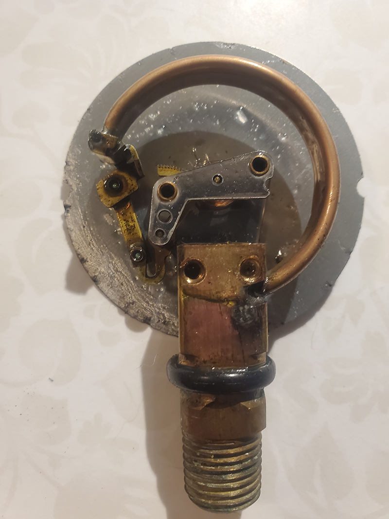
1 The inside of a bourdon tube pressure gauge. (Photos by author.)
PRESSURE GAUGES
Feedback in a control system is critical to making decisions to maintain the process, whether the controller is a human operator or a computer controller. The most common feedback device on a pump panel is the bourdon tube pressure gauge, invented by French scientist Eugene Bourdon. The heart of the pressure gauge is the bourdon tube, a C-shaped metallic tube sealed at one end and open to system pressure at the other. When pressure is applied to the tube, it attempts to straighten; the degree of this is determined by the material and construction of the tube. The deflection of the tube is translated to rotational motion through linkages and gears. The gears are connected to a shaft to move the needle on the gauge face. If water freezes in the tube, it will straighten the tube to the point that it will not return to the proper shape, and the gauge will be unable to accurately measure pressure.
Gauges come in a variety of sizes, pressure ranges, and accuracy. National Fire Protection Association (NFPA) 1900, Standard for Aircraft Rescue and Firefighting Vehicles, Automotive Fire Apparatus, Wildland Fire Apparatus, and Automotive Ambulances, outlines the requirements for master pressure gauges. The master intake gauge should have a range from 30 inches of mercury (in. Hg) vacuum to a minimum of 300 pounds per square inch gauge (psig). The master discharge gauge should have at least a range of 0 to 300 psig. Both master gauges should be a minimum of 1 inch in diameter larger than the individual discharge gauges. The accuracy of the master gauges should be grade 1A based on the ASME B40.100 standard having an accuracy of 1% of full scale in all sectors. Gauge accuracy breaks the gauge into three sectors: the first 25%, the middle 50%, and the last 25%. The middle 50% is to have the greatest accuracy. This is why the range of a gauge must be selected to have the normal operating pressure in the middle 50% of the range. If digital gauges are used, they should have an accuracy of 3.5%. Accuracy of pressure measuring devices is based on the full range of the gauges. A 2% accuracy gauge having a range of 400 psig could have a potential variation of 8 psig in the positive or negative direction. It may not seem like much, but remember each story of elevation is estimated at 5 psig. Even with a 2% gauge, the reading could be off by more than a floor of elevation.
Discharges 1½ inches and larger must have an individual discharge gauge. These gauges must be tapped into the plumbing downstream of the valves. It makes perfect sense that gauges are downstream of the valves; otherwise, it would be impossible to use them for gating down the valves, and they would read the same as the master, with the exception of loss in the plumbing. Manufacturers have started tapping the gauge lines at the drain, making it important to pay attention to the oft-forgotten drain (more on this later). Individual discharge gauges must be of grade B accuracy, meaning ±3%/±2%/±3%—in other words, the center 50% of the gauge is the most accurate at 2% and the outer 25% are only 3% accurate.
Based on the NFPA requirement, what discharge almost never has a discharge gauge? The tank fill discharge rarely has a gauge, even though many are 1½-inch and should, based on the standard. Polypropylene tanks have a fill pressure limit of 100 psig. Without a gauge, how does the operator know how far to gate down the tank fill to keep the pressure less than 100 psig when flowing other discharges? The answer is the operator does not know the pressure going to the tank—the pressure of the master discharge gauge shows the maximum discharge pressure. Not only does keeping the pump-to-tank gated keep the pressure below 100 psig, it prevents too much water from being diverted from firefighting efforts. Some practice and experimentation are needed to determine how far to gate the tank fill. A better idea is to start specifying gauges on tank fill.
Because most engines do not have flow meters, pressure gauges are the feedback operators use to determine if the correct flow is going to the handlines. An operator must have basic hydraulic knowledge to be effective. At a minimum, the operator must interpret and, if needed, manipulate a pump chart to get the proper pressure for the handline flows. There are those who believe in rule-of-thumb pump operations: thumb up for more pressure and thumb down for less pressure. The radio equivalent is the nozzleman on the radio yelling for more pressure. If the operator blindly increases pressure without knowing the correct pressure for a particular handline, fatal issues could be missed. Admittedly, there are situations where a little more pressure is needed, but it needs to be reasonable. A request for 5 to 10 pounds over the chart pressure can be expected. If the request gets over 10 psig from the chart, the operator needs to walk the line and make sure there is not a pile of spaghetti in the front yard restricting the flow. If the crew keeps calling, and pressure just does not increase, the line may have blown—check this and let command know. Gauges can be used to “see” what is going on in the fire building. It is the operator’s responsibility to be an extra set of eyes for command and safety.
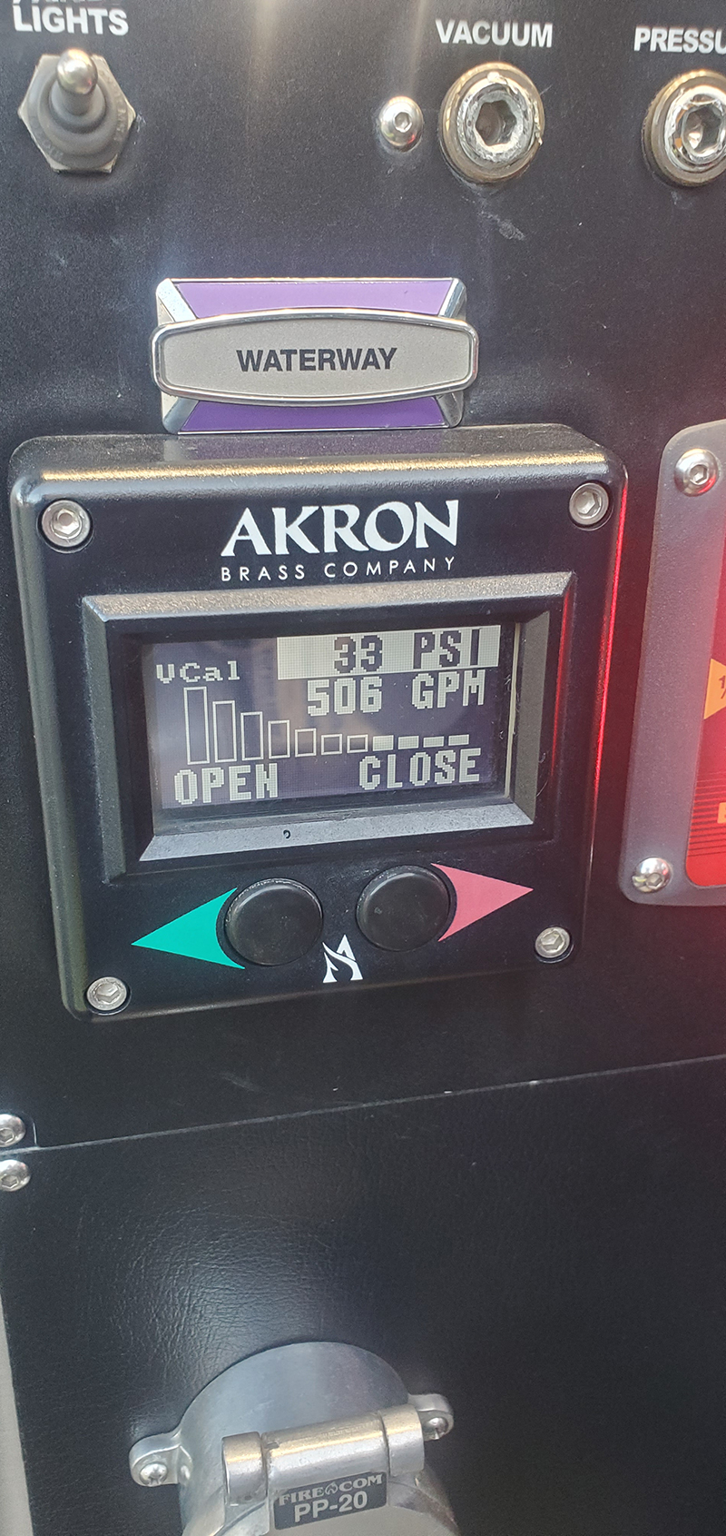
2 An aerial waterway flow meter.
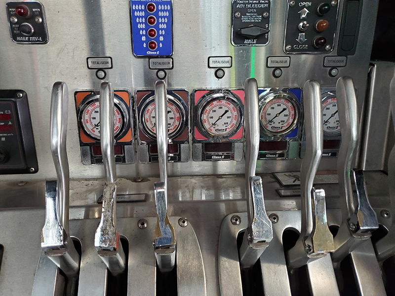
3 A pump panel with individual flow meters.
FLOW METERS
It would be great if every discharge on every engine had a flow meter to directly tell the operator the flow in each line. Many factors create the lack of flow meters on engines, and the biggest is cost. Flow meters cost substantially more than a pressure gauge, and even with a flow meter, a pressure gauge is required on the discharge. This is because the same flow can be developed at various pressures, and events can occur to alter the proper match of flow and pressure. Some rules for installing flow meters include that they should be installed six pipe diameters downstream of an elbow and no closer than one pipe diameter from a valve. With just these two rules, one can see it is difficult to fit this all in the confines of the pump house. A distance 6 times a 2½ inch pipe is 15 inches of pipe. Given the tightness of most pump houses, adding this length is hard to imagine. To counter imperfect installation, calibration is required annually. This is a recurring expense for a department. Flow meters are usually found for aerial waterways and foam systems. Having them on waterways prevents the need for knowing the exact height to determine elevation head and the friction in the waterway, which depends on how many sections are extended and how far each is extended. It is easier to have a direct reading in this case. Foam systems require flow meters to inject the correct proportion of foam into the manifold. Even when foam is not being injected, the system is measuring water flow to the manifold. If foam lines are being used, the operator can read the total water flow going through the foam system. One line will give a direct reading, but two will require making sure pressures are equal and dividing the flow value between the two lines.
ENGINE PARAMETERS
The tachometer, analog or digital, provides feedback on how fast the engine is turning. Normally, we do not think much about this—just keep increasing the revolutions per minute (rpm) until the correct pressure is achieved. But, it can tell the operator valuable information about how the pump is behaving. Increasing the rpm with no increase in pressure is a leading indication that cavitation is imminent. Having to use higher rpm to achieve similar flows during a pump test points to damage in the pump, making it less efficient, or the engine dropping in power.
Other important engine feedback on the pump panel, including engine oil pressure, engine coolant temperature, and system voltage, is required by NFPA 1900. These can be in the form of gauges or LED indicators with the values being accessible in a scroll-through menu. One critical piece of feedback missing from the NFPA standard, especially on longer operations, is a fuel gauge. While not required, many departments spec a fuel gauge on the pump panel to prevent the operator from having to go to the cab to check the level. Even without a gauge on the pump panel, there may be an audible alarm to let the operator know the fuel level is low. It is important to know if your apparatus has this feature before the operator starts hearing buzzing at the control panel and wonders the source.
TANK LEVEL
A very important piece of feedback on the pump panel is the tank level gauge. Most interior attacks are initiated with the water we show up with in our tanks. It is critical to the operation and crew safety that the operator knows how much water is in the tank and relays it to command when it gets to ½ and ¼ full. This is the clock the operator has to work against to secure a water supply. These markers depend on standard operating guidelines and tank size, but it is something the operator needs to be acutely aware of. Tank level gauges work off a pressure transducer in the bottom of the tank. Many level gauges use the tank pressure head along with a microcontroller programmed with the tank geometry to determine the actual level. Like all things electronic, this can fail. What is your backup? The best is timing how long it takes to empty the tank flowing each preconnect combination on the engine. Do not just calculate it, get out and flow it. Higher flows will cause a vortex in the tank at a higher level than lower flows. When the vortex pulls air into the intake, there is a loss of flow to the lines.
Another option is opening the hatch on the top of the tank and looking at the level. This is the proper way to check the water level during apparatus checks, as faulty level indicators can only be found this way. If the level gauge is the only reference ever used, there is no way to know when it is not working properly.
Part 2 will cover the control systems water contacts along the way from intake to discharge.
REFERENCES
Bourdon Instruments. (n.d). Retrieved on January 18, 2024 from https://www.bourdon-instruments.com/be/en/product-overview/pressure-gauges/c/36822.
NFPA 1900, Standard for Aircraft Rescue and Firefighting Vehicles, Automotive Fire Apparatus, Wildland Fire Apparatus, and Automotive Ambulances (2024 ed.).
NFPA 1911, Standard for the Inspection, Maintenance, Testing, and Retirement of In-Service Emergency Vehicles (2017 ed.).
NFPA 1962, Standard for the Care, Inspection, Service, and Replacement ff Fire Hose, Couplings, Nozzles, and Fire Hose Appliances (2018 ed.).
“Power is nothing without control” celebrates 25 years. (2018) Pirelli. Retrieved on January 21, 2024 from https://www.pirelli.com/global/en-ww/life/innovation/industry/-power-is-nothing-without-control-celebrates-25-years-52060/.
Gauge Accuracy. (n.d). Winters Instruments. Retrieved on January 18, 2024 from https://winters.com/engineering/gauge-accuracy.
Edward Collet has been a member of the Canal Fulton Lawrence Township (OH) Fire Departments since 2002. He is a co-chair of the Ohio Fire Chief’s Water Supply Technical Advisory Committee. Since 2019, he has been involved with instructing firefighters in Kenya with Africa Fire Mission. He is an instructor at the Ohio Fire Academy focusing on water supply and pump operations. He has a bachelor’s degree in mechanical engineering from the University of Akron, a master’s degree in engineering management from Ohio University, and an MBA from Liberty University.

